Specification:
Item Type: SDR Development Board
Material: PCB
Basic Parameters:
Design Frequency: 1MHz-6000MHz
Data Bandwidth: 20MHz
Sampling Accuracy ADC DAC: 8bit
Sampling Rate ADC DAC: 20Mbps
Data And Power Supply Interface: USB2.0
Open Source Level: Fully Open Source (software, hardware)
RF Indicator:
Maximum Transmission Power: 10dBm (less than the minimum stray transmission power according to radio regulation)
Maximum Receiving Power: -5dBm (Note: Exceeding this value will burn the board)
64QAM Emission EVM: 1.5%
Multiple Sampling Bandwidth: 20MHz
Main Hardware:
RFFC5072: Mixer provides local oscillator signals from 80MHz to 4200MHz
MAX2837: 2.3GHz to 2.7GHz wireless broadband RF transceiver
MAX5864: ADC DAC, 22MHz sampling accuracy 8bit
LPC4320/4330: For ARM Cortex M4 processor, 204MHz
Si5351B: I2C programmable arbitrary CMOS clock generator with 40MHz and sampling clock provided by 800MHz division
MGA 81563: 0.1-6GHz 3v 14dBm amplifier
SKY13317: 20MHz-6.0GHz RF Single Pole 3 Throw (SP3T) Switch
SKY13350: 0.01-6.0GHz RF Single Pole Double Throw (SPDT) Switch
Take the receiving process as an example, after the signal enters from the antenna, the process is as follows:
The RF switch determines whether to amplify through a 14dB amplifier
The signal is high pass or low pass filtered by an image suppression filter
Signal processing udrffc5072 chip is mixed to 2.6GHz fixed if
If the range is 2.150ghz-2.750ghz
Signal input MAX2837 chip mixing to baseband, output differential aliqsignal
The MAX2837 chip can limit the signal bandwidth
The max5864 chip digitizes the baseband signal and sends it to cpld and microcontroller for all repair
The LPC4320/4330 processor sends the sampled data to the computer via usb
Put the RFFC5072 and MAX2837 in the shielding cover to protect them from interference from the outside world and other chips on the board, and try to avoid some chips from electrostatic breakdown
Features:
Operating frequency from 1MHz to 6GHz
Half duplex transceiver
Up to 20 million samples per second
8 bit orthogonal sample (8 bit i and 8 bit q)
Software configurable RX and TX gain as well as baseband filters
Software controlled antenna port power (50 mA at 3.3V)
SMA female antenna connector
SMA clock female input and output for synchronization
Convenient programming button
Internal row of pins for expansion
High Speed USB 2.0
USB Power Supply
Open Source Hardware
Features:
1Frequency Range: Fully open source software radio development platform with a wide frequency range of 1MHz6GHz, supporting for Windows, for Linux, for OS X, for Android, and other systems. 2Multiple Functions: With working frequency band, filtering, mixing signal amplification, modulation and demodulation type, data format, encryption mode, comm protocol and other functions. 3Main Purpose: Designed to support modern and next generation radio technology testing and development, it can be used as a USB peripheral or programmed for independent operation. 4High Efficiency: This SDR platform development board uses a half duplex transceiver, with up to 20 million samples per second, with high operation efficiency, and compatibility with most software. 5Easy Installation: With exquisite craftsmanship, this development board has standard interfaces and mounting holes, making it easy to install and program, meeting more DIY development needs.
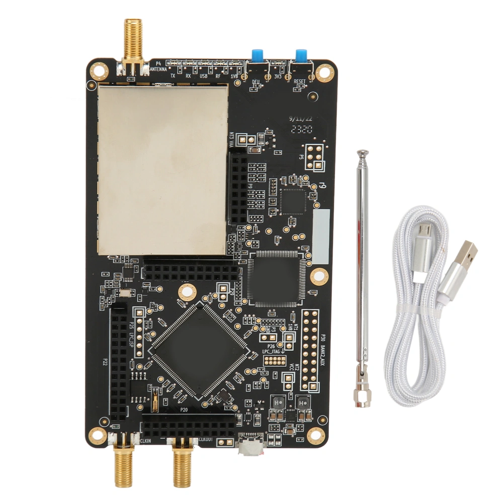
Package List:
1 x Mainboard
1 x Antenna
1 x Data Cable