Description
This pair of a speaker works simply excellent in car audio application; especially when they are fed with an amplifier with proper setup. Made of quality material and manufactured with exquisite craft. You could diy it by yourself and show your creation.
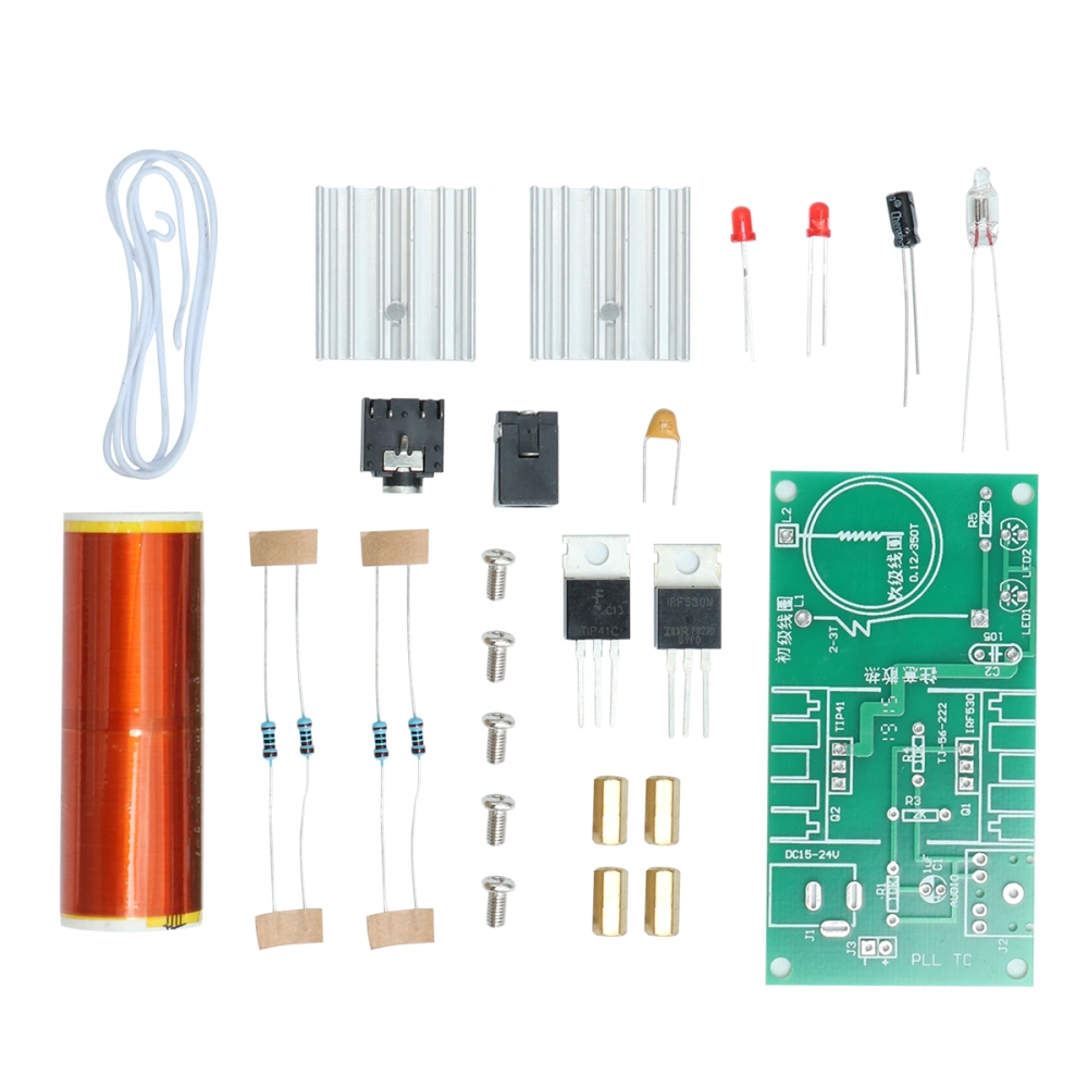
Feature- Color: As shown. - Material: Plastic. - Size: 8 x 5 x 0.1cm/ 3.15 x 1.97 x 0.039inch. - This pair of a speaker works simply excellent in car audio application; especially when they are fed with an amplifier with proper setup. - Made of quality material and manufactured with exquisite craft. You could diy it by yourself and show your creation. - Tesla's lamp function: after the tesla coil is charged, the fluorescent lamp can be lit. - Tesla produces an arc: the rear end of the wire will produce an arc. The arc can also ignite! First check and identify each component against the component list. First install 4 color ring resistors, and the mounting position of each resistor on the board is printed with a resistance value. Install monolithic capacitors, the are not divided into positive and negative poles. Installation of electrolytic capacitors requires attention to distinguish between positive and negative. If you encounter an electrolytic capacitor that has been shortened, then Can pass this white area on the body of the electrolytic capacitor Field to determine the pin of the negative. This through the top The white strip is on the side of the negative pin. Install the location of the electrolytic capacitor, note There is a "+" on the side of the positive pole. It is a hollow semicircle and the negative side is Solid semicircle. Install the electrolytic capacitor on the PCB (Note: This electrolytic capacitor is used to couple the sound signal into the Tesla coil circuit, if not installed, The circuit can also work normally, but it cannot play back the sound from the coil). Install two LEDs The long legs of the LED are positive, the short legs are negative, and the triode and FET are installed. First fix the two transistors to the two heat sinks with two M36 screws. The corresponding transistor characters are printed on the corresponding mounting position of the circuit board. Since the two transistors have the same shape, the installation is first determined. Must be seated. Install the DC5.52.1 power socket and 3.5mm jack audio jack. Attach the copper posts to the four corners of the board. Installing the secondary coil The secondary coil is made of a thin copper wire of 0.12 mm diameter and tightly wound on a 2CM diameter PVC tube. The coil has a long lead at one end, a short end, and a short lead end is tinned. If you find that it is not tinned, you must use it first. The scrapes off the insulating paint at the end, paying attention to the action and avoid breaking the copper wire. Place one side of the short lead of the secondary coil down on the corresponding position on the board, and make the end of the short lead just at the board character L2 to facilitate soldering. When the secondary coil is subsequently fixed, it is important to know that the lead is not long enough to be connected to the L2 position. Use a hot melt adhesive, adhesive such as 502 to secure the primary coil to the board, and solder the short end of the secondary coil to L2. Manually winding the primary coil. Flatten the thick copper wire and solder one end to the L1 position. 2. The thick copper wire is wound around the secondary coil counterclockwise for 3 turns. Then fold down, reduce the excess part of the welded end, and then adjust the interval between the primary coil and the secondary coil to be more than 5mm. If the interval is too small, there will be a fire between the primary and secondary, and the secondary coil will be burnt if it is severe.